


Electronics · A VIEOX perspective
PCB fabrication: preserve the story inside the bare board.
Follow bare printed circuit board fabrication through approved data, material stackup, drilling, plating, inspection and electrical test before assembly.
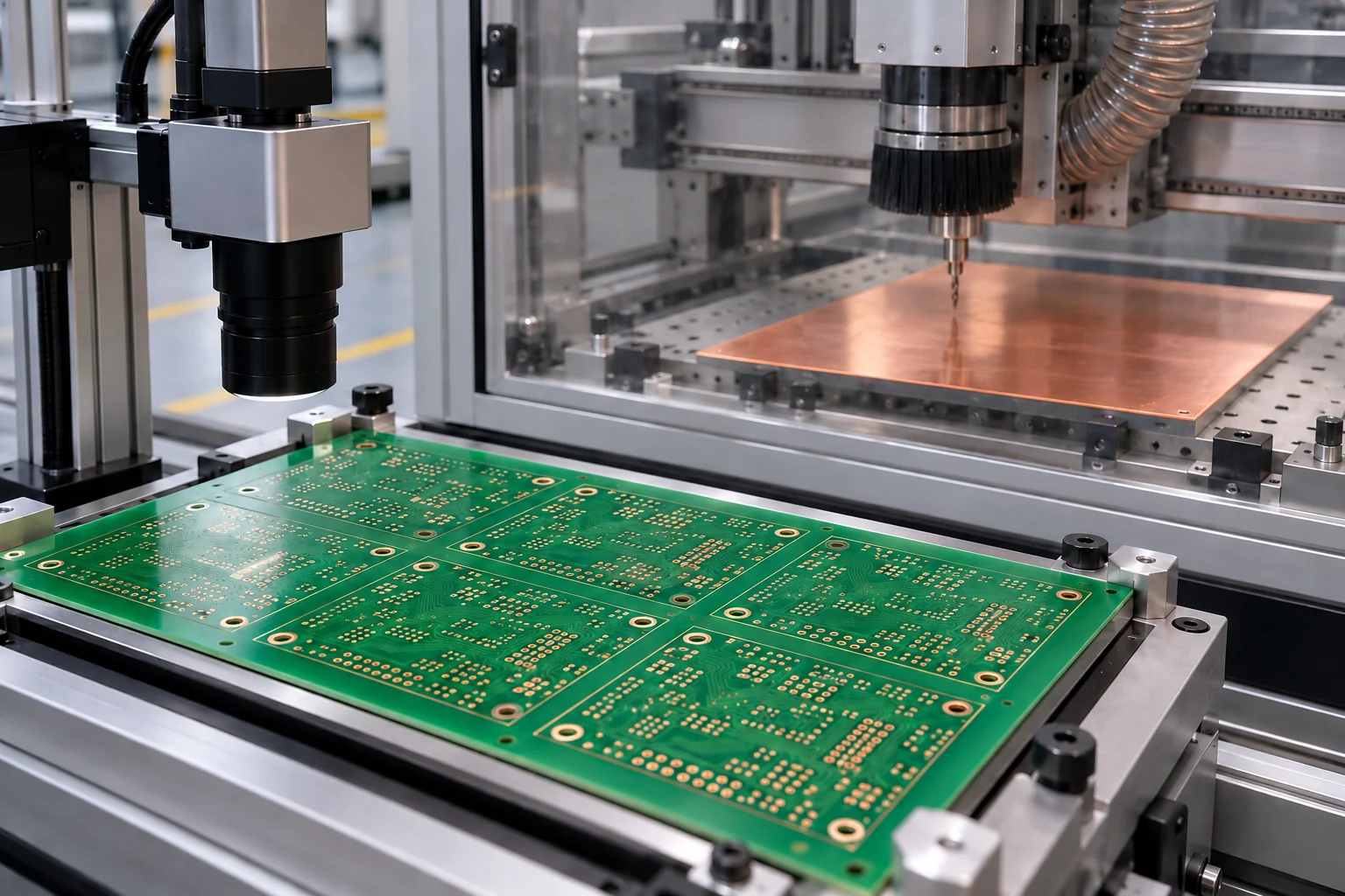
The practical question
What should manufacturers preserve across bare PCB fabrication?
Keep the released design and approved material construction connected to each manufacturing lot, panel and relevant inspection record. Follow the actual fabrication route, including layer alignment, holes, plating, surface finish and electrical testing. Make supplier deviations and sampling boundaries visible so the receiving team knows what the evidence covers and what remains to be checked.
A bare printed circuit board (PCB) is already a manufactured product before components are fitted. Its copper connections, insulating structure, holes and protective finishes emerge through several dependent operations. Following that history helps the assembly team distinguish a fabrication concern from something introduced later, without treating every electrical failure as a soldering problem.
Define the bare-board handover
PCB fabrication produces the board structure and its electrical connections. Printed circuit board assembly (PCBA) adds components and their connections to that board. A fabricated board can therefore pass its agreed checks while still requiring assembly inspection, programming and functional testing before it becomes part of usable equipment.
Define the handover between the fabricator and assembler. Agree the board revision, supplied quantity, identification method, packaging requirements and acceptance evidence. Establish how questions return to the design owner. A purchase order and a drawing with similar names are insufficient when one contains an unapproved change or a different layer arrangement.
Make the layer construction an approved decision
A stackup describes the arrangement of conductive and insulating layers through the board. Review it with the fabrication drawing, material specification, copper requirements, finished thickness and any controlled electrical characteristics. Record which requirements are essential to the design and which choices the fabricator is authorised to make.
Keep engineering questions and their approved answers with the released data package. If a material becomes unavailable, a proposed replacement should return through the agreed evaluation process. Similar catalogue descriptions do not establish equivalence for a particular product. Preserve the approved construction actually used, so a later investigation does not depend on the latest revision alone.
Connect drilling and plating with the panel history
Eurocircuits describes checks of drilled-hole position against inner layers, followed by hole-wall preparation and copper-plating checks. These steps connect geometric alignment with the conductive path through the board; they need to be interpreted together.
Retain panel identities, programme revisions, process exceptions and inspection results. Check how restarts and reprocessed panels enter the record. Compare observations with the approved board requirements rather than borrowing dimensions or process settings from a different product.
Sources: [1]
Separate electrical continuity from complete acceptance
Eurocircuits describes bare-board electrical testing against a reference netlist for shorts and open circuits. The netlist expresses the intended electrical connections. Its revision and origin therefore belong beside the test result.
Keep that result distinct from checks of board dimensions, soldermask alignment and the specified surface finish. Soldermask covers selected areas; the finish protects designated exposed metal for its intended use. Review the complete acceptance package rather than allowing one pass flag to stand for all required checks. Record unresolved discrepancies before the boards move into assembly.
Sources: [1]
Reconstruct one concern across the supplier boundary
Hypothetical example: an assembled controller develops an intermittent connection near a plated hole. The team locates the board lot, fabrication revision, relevant sample results and subsequent assembly history. It keeps the returned unit intact until the responsible specialists agree an examination plan, rather than immediately assigning the failure to the fabricator or assembler.
Start with a narrow question and preserve competing explanations. Compare affected and unaffected material using documented identities, then assign the next examination and the product-disposition decision. Record what the evidence rules out and what remains uncertain. VIEOX welcomes a discussion about the information needed to make this handover and investigation easier to follow.
Put the question to work
A practical checklist
- Distinguish the bare board from the populated assembly.
- Release the fabrication data and material construction together.
- Link panel identities with drilling, plating and inspection records.
- State what each sample or coupon represents.
- Keep electrical test separate from the complete acceptance decision.
- Preserve supplier questions, deviations and downstream investigation links.
Questions, answered
Does a bare-board electrical pass prove that finished equipment will work?
No. It addresses the connections covered by that test and its reference data. Component assembly, firmware, mechanical integration and product testing still introduce their own requirements and evidence.
Can an alternative laminate be accepted because the board outline is unchanged?
The design owner and responsible supplier reviewers need to evaluate the actual material and construction requirements. The outline alone does not describe the electrical, thermal or mechanical expectations for the board.